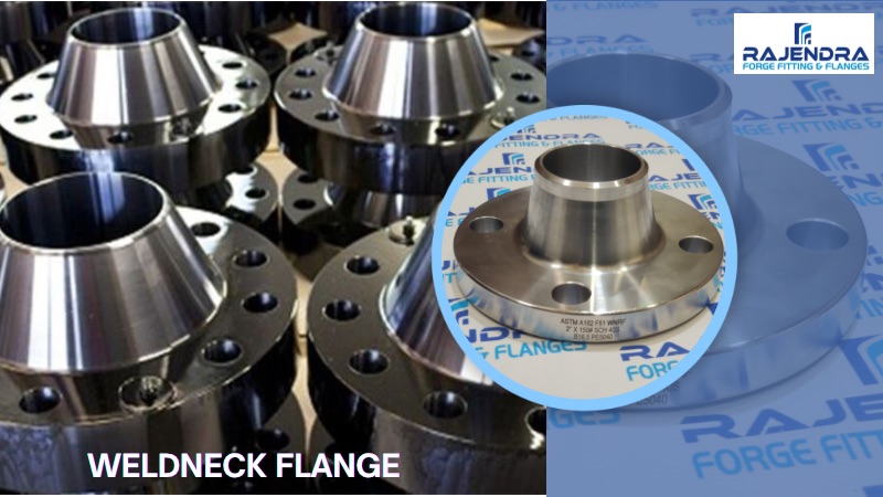
Weld Neck Flanges
Weld Neck Flange is flanges that designed to be joined to a piping system by butt welding. This kind of flange include lots of specification. Weld Neck Flange is expensive because of its long neck and cost of people for contact WN flange with pipeline or fitting but is preferred for high-stress applications. The necks, or hubs, transmits stresses to the pipeline. The gradual transition of thickness from the base of the hub to the wall thickness at the butt weld provides important reinforcement of the Weld Neck Flange. The bore of Weld-Neck flange matches bore of the pipeline, reducing turbulence and erosion.
A weld neck flange, also called a tapered hub flange or high-hub flange, is a kind of flange that can relocate stress to the pipes, ensuring a decrease in high-stress concentration at the bottom of the flange. There are two welding neck flanges designs – the first type is used with wipes while the second, longer type cannot be used with pipes but with a process plant. The weld neck flange comprises of a round fitting that extends beyond the rim of the circumference. These flanges, typically manufactured from forging, are actually welded to pipes.
Weight Chart
| NPS | Slip On |
Thd | Socket Weld |
Lap Joint |
Blind | Weld Neck |
| 1/2 | 0.5 | 0.5 | 0.9 | 0.5 | 0.9 | 0.9 |
| 3/4 | 0.9 | 0.9 | 0.9 | 0.9 | 0.9 | 0.9 |
| 1 | 0.9 | 0.9 | 0.9 | 0.9 | 0.9 | 1.4 |
| 1¼ | 1.4 | 1.4 | 1.4 | 1.4 | 1.4 | 1.4 |
| 1½ | 1.4 | 1.4 | 1.4 | 1.4 | 1.8 | 1.8 |
| 2 | 2.3 | 2.3 | 2.3 | 2.3 | 2.3 | 2.7 |
| 2½ | 3.6 | 3.6 | 3.6 | 3.6 | 3.2 | 4.5 |
| 3 | 4.1 | 4.1 | 4.1 | 4.1 | 4.1 | 5.2 |
| 3½ | 4 | 5.4 | 4 | 4 | 5.9 | 5.4 |
| 4 | 5.9 | 5.9 | 5.9 | 5.9 | 7.7 | 7.4 |
| 5 | 6.8 | 6.8 | 6.8 | 6.8 | 9 | 9.5 |
| 6 | 8.6 | 8.6 | 8.6 | 8.6 | 12.2 | 11.7 |
| 8 | 13.5 | 13.5 | 13.5 | 13.5 | 21.2 | 18.9 |
| 10 | 19.4 | 19.4 | 19.4 | 19.4 | 31.5 | 24.3 |
| 12 | 28.8 | 28.8 | 28.8 | 28.8 | 55.4 | 39.6 |
| 14 | 40.5 | 40.5 | 40.5 | 47.3 | 63 | 51.3 |
| 16 | 47.7 | 44.1 | 44.1 | 63 | 81 | 63 |
| 18 | 58.5 | 58.5 | 58.5 | 72 | 99 | 74.3 |
| 20 | 74.3 | 74.3 | 74.3 | 87.8 | 128.3 | 88.7 |
| 22 | 83.3 | 83.3 | 83.3 | 110.3 | 159.8 | 101.3 |
| 24 | 99 | 99 | 99 | 123.8 | 193.5 | 120.6 |
Dimensions, Weights & Tolerances
| Dimension | Condition | Tolerance |
|---|---|---|
| D | D ≤ 610 mm | ±1.5 |
| D > 610 mm | ±3.0 | |
| K | NPS ≤ 24 | ±1.5 |
| G | 2 mm RF | ±1.0 |
| 7 mm RF | ±0.5 | |
| B | NPS ≤ 10 | ±1.0 |
| 12 ≤ NPS ≤ 18 | ±1.5 | |
| NPS ≥ 20 | +3.0, -1.5 | |
| A | NPS ≤ 5 | +2.0, -1.0 |
| NPS ≥ 6 | +4.0, -1.0 | |
| X | X ≤ 610 mm | ±1.5 |
| X > 610 mm | ±3.0 | |
| Y | NPS ≤ 4 | ±1.5 |
| 5 ≤ NPS ≤ 10 | +1.5, -3.0 | |
| NPS ≥ 12 | +3.0, -5.0 | |
| T | NPS ≤ 18 | +3.0, -0.0 |
| NPS ≥ 20 | +5.0, -0.0 | |
| *BCC | NPS ≤ 2-1∕2 | 0.8 |
| NPS ≥ 3 | 1.5 | |
| *BHS | NPS ≤ 24 | ±0.8 |